Exploration of how robot arms work for my final project in my Electronic Systems (ELSY) class.
Rockets vs Robots
Originally, I planned to make a Trust Vector Control unit with an IMU (accelerometer, gyroscope, etc.) and GPS, but I scrapped the idea since model rocket engines are single-use, risky, and hard to test. So I chose to make a small (pinching) robot arm!
Overview
In my first design, I changed the position of the whole arm using a 4-bit binary digit as input where I mapped a digit to a specific pose of the arm. I abandoned this plan because I preferred to be able to manually control each servo motor and joint.
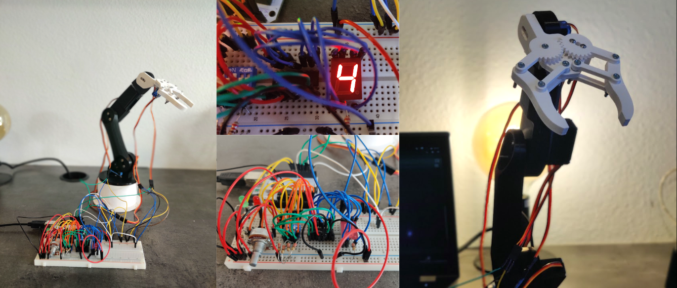
The final implementation uses the 4-bit digit input to select one of the six servo motors. You can then press a comfirm button and turn a potentiometer to rotate the selected servo. The implementation also features some visual feedback elements, such as a 7-segment display that shows the selected servo's number and two LEDs that indicate whether the servo is "listening" or not (toggle is done using the select button).
I also had to provide an external power source because the servos can draw up to 2 Amps when on maximum load.
A sped-up demo of the working arm can be found here.
Robot Arm Model
The model of the robotic arm is created and designed by How To Mechatronics and can be viewed and downloaded on Thangs.com.
Printing & Assembly
The models were printed by a friend of mine using a Prusa i3 Extruder 3D printer (thanks Sam). The total printing time was no longer than three hours.
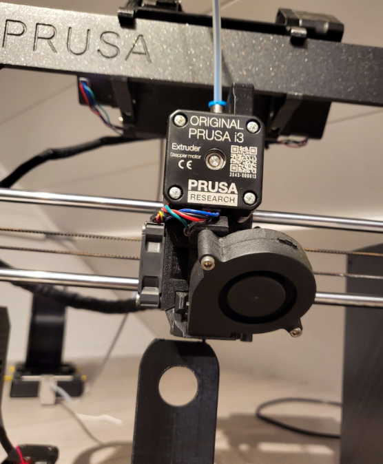
It took around four to six hours to assemble the arm itself. I also had to run to the store to get some more screws, nuts and bolts.
The "shoulder" servo, which takes the whole weight of the rest of the arm as well as the payload, would benefit from having some sort of spring or at the shoulder axis. That's why a rubber band is used.
Electronics & Circuit diagram
To select one of the six servo motors, I used a 4-pin DIP switch to represent the binary inputs. This makes a total of 24 or 16 possible combinations (0-15). When selecting a higher number than the available servos, no servo will be selected.
Like mentioned earlier, to rotate the selected servo a potentiometer is used. This is essentially a variable resistor that acts like a voltage divider. The electric potential (voltage) is measured by the Arduino and converted into a rotation in degrees for the servo motor.
The following component is a simple button. When said button is pressed, the Arduino selects the desired servo motor and writes the current (converted) potentiometer value to it. The arm is at rest when the button is released since the Arduino doesn't write anything to the chosen servo. Two LEDs, a green and a red one, are utilized as well to show whether the Arduino is writing or not respectively.
The output binary number of the DIP switch is also wired to an 74HC4511 Integrated Circuit. This code-converter IC converts a Binary-Coded Decimal to the respective values on a Common Cathode 7-segment display. Common cathode signifies that a high voltage is required to turn on an LED.
I utilized the more powerful MG996R* servos for the first three axes—the waist, the shoulder, and the elbow—and the less but still powerful SG90* micro servos for the gripper and the other two—wrist roll and wrist pitch. Both types of servos are sold and manufactured by the company AZDelivery*. These servos can be controlled using a PWM signal or the Servo library on the Arduino.
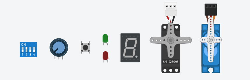
All the electronics I discussed above, from left to right: DIP switch, Potentiometer, Button, LEDs, 7-seg display, Servos.
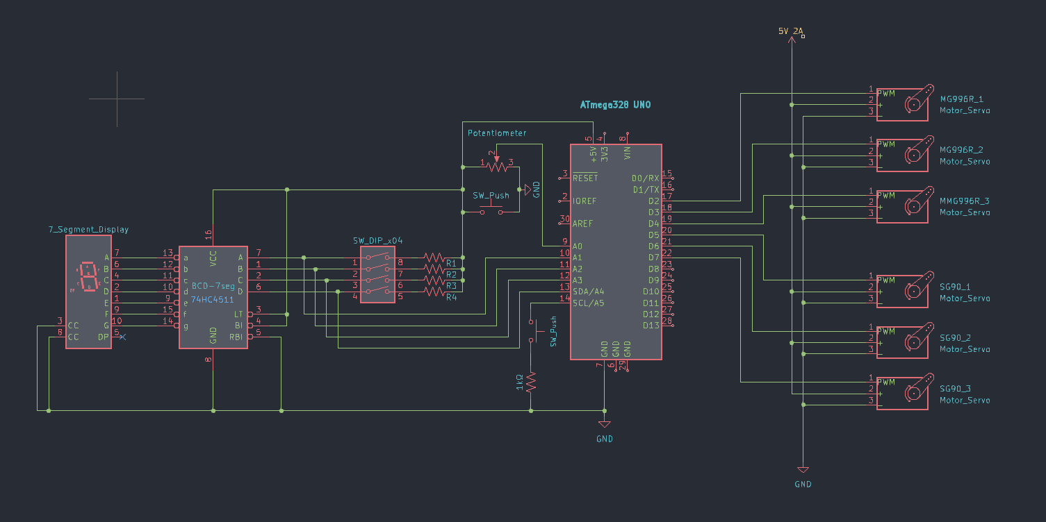
Below you can find the KiCad schematic of the whole project.
Arduino Setup
The source code of this project can be found on my GitHub.
A switch or button has the ability to create and break contact repeatedly in a brief period of time. This is caused by the "springing" or "bouncing" of the metal part of the switch or button. This can be remedied with a technique called "Debouncing" and can be implemented in an analog, digital or software form.
In the software solution we just update the state of the button when a certain amount of time has passed. The following code accomplishes this.
  buttonPressed = digitalRead(buttonPin);

 if (buttonPressed != lastButtonState) {
    lastDebounceTime = millis();
  }

  if ((millis() - lastDebounceTime) > debounceDelay) {
    if(buttonPressed != currentButtonState) {
      currentButtonState = buttonPressed;
    }
  }
After the correct button state has been established, we move into the main functionality, which will first determine whether the button is pressed.
if (currentButtonState) {
    // Read & convert DIP value
    currentServoId = fromBinaryToDigit(DIPbit3, DIPbit2, DIPbit1, DIPbit0);
    currentServo = findCurrentServo(currentServoId);

    // Read & potentiometer value
    servoAngle = getServoAngle(potentioValue);

    // Write to correct servo
    currentServo.write(servoAngle);
}
And that's it, all of the equipment and software that I used or this project!
*Any redirect to products or webshops are NOT affiliate links. I do not earn anything by linking said products.